Background
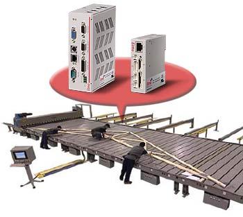
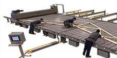
A wide range of equipment is available today to automate the truss manufacturing process. In the final stage, automated jigging tables can be used to help assemble pre-cut truss members into the final product using. These tables use screw-driven pucks are used to hold the truss members in place based on a computerized truss design while assemblers attach fastening plates.
Such jigging table systems vary in size according to the specific trusses that are being built. To meet this need for scalability, the systems are built from table modules which include four servo-driven pucks and a dedicated control cabinet.
Operators select and manipulate the truss’s position from a computer terminal and, when it is ready, they simply press a button to send the system’s automated pucks into place. Operators can also divide the overall system into smaller groups to allow multiple trusses to be built in tandem.
Once the truss is laid out and the fasteners have been applied, an operator locks the fasteners in place by driving a mobile press over the truss. Pneumatic lifts are located between each table and, when the truss is complete, an operator activates the appropriate lifts from the mobile press, lifting the truss out of the pucks and off the tables.

The Challenges
This project presented several challenges including greater scalability, additional features, and reduced cost. Some specific requirements included:
Conversion from Existing Equipment
- AC Induction motors
- Variable frequency drives
- PLC control
- Profibus networking
Run-time Routines
Each axis must be able to perform the following motion routines:
- Move to truss position
- Unclamp from truss position
- Hard-stop homing
- Offset calibration
- Forward/reverse jog (via controller command or jog switch on a table’s control cabinet)
Additional Features
- Group and Individual Commands: Regardless of the number of axes in a system, the control system must be able to command multiple axes simultaneously.
- Group Reassignment: The control system must be able change axis groupings on the fly.
- Connectivity: The control system requires a robust communication protocol which can network 4-100 axes and interface with the system’s PC hardware with minimal software development.
- I/O Assignment: Critical system I/O (E-stop/Reset) as well as lift-out I/O must be recognized by the control system must be configurable during the installation.
- Diagnostics: Detailed diagnostic information must be available to operators so that they can carry out troubleshooting activities.
- Error Handling: Robust error handling must be in place to reduce downtime.
- Auto-configuration: When new or replacement drives are installed, the control system must automatically commission the new node.
The Solution
Elmo’s Maestro was to chosen to network and control the motion control system, which can contain up to 100 servo axes. The Maestro is a gateway between an Ethernet network and CANopen and also provides network supervision and control capabilities. The Maestro was able to provide connectivity between the operator’s computer and the motion system without significant software development.
Elmo’s Harmonica intelligent servo drives provide the power and position control capabilities for each axis of resolver-based brushless servo motors. The Harmonica’s programmability allows all of the required motion routines (move to position, home, jog, etc.) to be provided as functions resident in each axis. In this application, operators can call up motion routines from the GUI (graphical user interface); toggle switches are also provided on the tables’ control cabinets to allow operators to manually jog the pucks into position.
Unique to Elmo is the ability to address drives as either a single node or as a part of a larger group. In this application, the types and sizes of trusses being made on a table system determines how axes are grouped together. This allows a group of (up to) 100 axes to be commanded with a single CANopen message, which eliminates unnecessary bus traffic and latency. This group command mode, when combined with the Harmonicas’ programmed routines, allows operators to move, jog, & home a whole group of drives simultaneously.
Users can define and manage these groups using a combination of the Maestro’s built-in features as well as application specific programs on the Maestro, Defining the specific axes that are in each group can be done on-the-fly, allowing the customers to easily divide their table system into smaller groups.

Reduced Downtime
Rapid Implementation
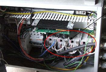
Intelligent, distributed control is ideal for this application and has significantly reduced the complex wiring in earlier, centrally controlled systems. As stated earlier, each 4-axis table has its own control cabinet. Motor, power and feedback cables are very short and connected directly to the Harmonicas. An off-the-shelf, shielded, CAT5E cable is all that is needed to connect each drive to the CANopen network.
Elmo’s technology allows users to store drive configurations and programs as a portable application file. Since each axis in this application is identical in terms of the motor/tuning parameters and the required motion routines, the same file is used for every axis.
The Maestro API (application programming interface) provides functions to download the full application file to all networked drives. During development, this feature was used to configure and update all of the system’s Harmonicas at once. This capability allows the customers to also update their entire drive system with the touch of a button!
In the very first system commissioned with Elmo’s motion solution, the simplified wiring and software setup allowed us to move the system within an hour of applying power!

